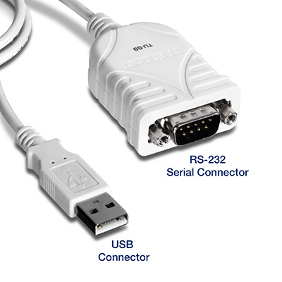
Div_647 - 0 items Shop By Category Shop By Application More ways to Shop 9-Pin D-Sub Cable (DB9) 9-Pin D-Sub Cables (DB9) -- 9-Pin D-Sub cable assemblies by Amphenol provide the perfect I/O solution for your DB9 d-sub equipped devices. The DB9 D-subminiature interface is typically used for RS-232 serial communications between PC's and peripheral devices. Free Download Epson L100 Reset Key there.
Download Aplikasi Kasir Sederhana Berbasis Php 1.8.1. Pinout of Epson Serial/RS-232 Cable DB9 to DB25 and layout of 9 pin D-SUB male connector and 25 pin D-SUB female connectorfor Epson Thermal/Impact Receipt Printer Cable Pinouts.
Php Login System there. All of our 9-pin d-sub cables come fully populated with 24K Gold plated contacts, molded DB9 connectors, and offer varying degrees of shielding depending upon your specific requirements. Please choose from our selection of 9-pin dsub (DB9) cables below: 9-Pin (DB9) Deluxe D-Sub Cable - Copper Shielded - Male / Female.
Example cables for connection from a PC to various Lantronix products with DB connectors are provided near the end of this FAQ Background: When RS232 was developed the idea was that there would be 2 kinds of devices, DTE (Data Terminal Equipment) and DCE (Data Communications Equipment). Everything would use DB25 connectors and everyone would always connect a DTE to a DCE using a straight-through cable and everything would be easy. However, as time went by folks wanted to connect two DTEs (or two DCEs) to each other, and connectors started being used, so alternative cable wirings were required. There are no hard and fast rules but in general a DTE will have a male DB25 or possibly a male DB9 connector and a DCE will have a female DB25 or DB9. Other connectors may be used but these are the most common. A typical DTE is a serial port on a terminal, a Com port on a PC or the serial port on an EDS2100.
A typical DCE is the serial port on a modem or on a UDS-10, UDS100 or UDS1100. If you're connecting a DB25M DTE to a DB25F DCE you can use a straight-through cable, i.e. Pin 1 wired to pin 1, pin 2 wired to pin 2, etc. Because of this DTE connectors are labeled according to the signal on the pin, DCEs are labeled according to the signal that should be coming from the DTE. In other words a DCE and DTE are labeled identically even though the direction of their signals are opposite. The most common DB25 pinout is: 1 Protective ground 2 Transmitted data (Out) (TD or TXD) 3 Received data (In) (RD or RXD) 4 Request to send (Out) (RTS) 5 Clear to send (In) (CTS) 6 Data set ready (In) (DSR) 7 Signal ground (SG) 8 Carrier detect (In) (CD or DCD) 20 Data terminal ready (Out) (DTR) Originally all 25 pins of a DB25 were used but today the above pins are usually the only ones used.
The most common pinout for DB9 serial connectors is: 1 Carrier detect (In) (CD or DCD) 2 Received data (In) (RD or RXD) 3 Transmitted data (Out) (TD or TXD) 4 Data terminal ready (Out) (DTR) 5 Signal ground (SG) 6 Data set ready (In) (DSR) 7 Request to send (Out) (RTS) 8 Clear to send (In) (CTS) 'Straight-through' cable So a cable for a connection from a DB25 DTE to a DB25 DCE is wired: DTE DCE DB25M DB25F DB25M DB25F TXD 2>------------>2 TXD RXD 3------------>4 RTS CTS 5---------->20 DTR To connect a DB9M DTE (e.g. The Com Port on a PC) to a DB25F DCE (e.g.